Panel Configuration Files
Contents
|
|
|
Related Links
|
Overview
The primary folder used by the panel system is the Panel folder. This folder contains the panel background image files (.bmps) and the panel configuration file (Panel.cfg). When an aircraft is loaded into the simulator, it also loads the appropriate panel configuration file. If you have more than one version of an aircraft and you want a different panel layout for the second version, you will have more than one panel folder. The name of the default panel folder is Panel. Additional panel folders must have the name Panel.xxx, where xxx is an identifying key.
For example, the Mooney Bravo ships with Panel and Panel.g1000 folders for the regular and galss-cockpit panels. The identification key is found in the Aircraft Configuration File.
[window titles]
The Panel system creates the aircraft's panel windows from the information in this
section. The variables are used to set the initial state of each panel window
and each interior view. For each WindowNN variable in this section, the Panel system
creates a panel window. It starts with Window00 and creates panel windows until
it reaches Window63 or until it finds a break in the progression.
When creating the panel window, the system looks for corresponding [WindowNN] sections
later in the configuration file. After the panel window is created, the gauges listed
in the [WindowNN] section are loaded.
Note
- Use the marks "//" to add a comment, or comment out a line you do not wish to be processed, in the panel.cfg file.
| Property | Description | Examples |
|---|---|---|
|
window00 to windowNN |
The list of panels for the aircraft. The order in which you assign panel windows
does not matter, so long as you start with window00.
The string you assign to each WindowNN line (for example, Window02=Radio Stack) is the title displayed for the panel window in Prepar3D when it is undocked. The string is also displayed on a submenu menu when you click Instrument Panel on the Views menu. You should therefore make sure the label you use for each window is appropriate. |
Window00=Main Panel Window01=Radio Window02=Fullscreen PFD Window03=Throttle Quadrant Window04=Compass Window05=Mini Panel |
[windowXX] and [vcockpitXX]
This section describes a panel window, including its shape, position, properties, the background image, and what gauges belong to the panel. The same structure is used for Virtual Cockpits, with the single addition of the texture parameter.
| Property | Description | Examples |
|---|---|---|
| file | Specifies the bitmap file to load and use for the panel window background (1024 by 768 resolution). This .bmp file must be in the same directory as the Panel.cfg file. |
file=Radio_Stack_bg.bmp file=HBH_713_background.bmp |
| file_1024 | The bitmap file to use when the screen width has been set by the user to more than 800. |
file_1024=panel_background.bmp file_1024=Air2S_background.bmp
|
| size_mm | A definition of the unit size used for placing and sizing gauges on this panel. For example, if the size_mm is 200 x 200 and a gauge's size is 50, 50, it will take up 1/16th ( ¼ x ¼) of the panel window. If no size_mm is defined, the size of the panel's background bitmap (not the gauge's background bitmap) will be used. If no background bitmap is defined (as is often the case with popup panels that contain only one gauge), a default size of 100 x 100 is used. If window_size is not specified, the size of the window on screen will be size_mm divided by the size_mm for the first window specified in the panel.cfg. For example, if the size_mm for a given panel is 200, 200 and the size_mm for the first panel in the panel.cfg is 1024 x 768, the given panel would occupy 19% of the screen in the x dimension and 26% in the y dimension, or a total of 5% of the total screen area. |
size_mm=1024 size_mm=1024,768 |
| position |
Specifies the relative position of a panel window to the main window. A number from
0 to 8 (as shown below) designates the position of the panel window. If nothing
is specified, 7 is the default, otherwise, one of: 0 = upper-left corner 1 = upper-middle side 2 = upper-right corner 3 = middle-left side 4 = middle 5 = middle-right side 6 = lower-left corner 7 = lower-middle side 8 = lower-right corner. |
position=7 position=8 |
| visible | Set to 0 if the panel is not visible by default. The default is 1 (visible). |
visible=1 visible=0 |
| always_visible | Set to 1 to enable panel to always display, even when switching views. If panel is closed it must be manually reopened to once again automatically display when switching views. The default is 0. |
always_visible=1 always_visible=0 |
| ident |
Specifies a unique identifier to define the panel window. You must have an ident
for each panel window. Valid entries are the following: MAIN_PANEL MAIN_PANEL_ALTn (where n is 1 to 9) THROTTLE_PANEL RADIO_STACK_PANEL COMPASS_PANEL MINI_CONTROLS_PANEL ANNUNCIATOR_PANEL ANNUNCIATOR2_PANEL IFR_MAIN_PANEL COLLECTIVE_PANEL GPS_PANEL OVERHEAD_PANEL PARKING_BRAKE_PANEL FLAPS_TRIM_PANEL FUEL_PANEL ELECTRICAL_PANEL TRIM_PANEL LANDING_GEAR_PANEL MISC_POPUP_n (where n is 1 to 10) MINIPANEL If your panel windows description does not fit any of above, use any number between 10000 and 19999. Lower and higher numbers are used internally. There should be a MAIN_PANEL for every aircraft, otherwise other panels may not be rendered correctly. |
ident=MAIN_PANEL
ident=THROTTLE_PANEL ident=ANNUNCIATOR_PANEL ident=OVERHEAD_PANEL ident=MAIN_PANEL_ALT1 ident=MAIN_PANEL_ALT2 ident=MINIPANEL ident=IDENT_MISC_POPUP_1 ident=270 ident=MISC_POPUP_1 ident=COLLECTIVE_PANEL |
| background_color | Use for a background created with no background bitmap. Use 0,0,0 for a transparent background. |
BACKGROUND_COLOR=16,16,16 BACKGROUND_COLOR=0,0,0 |
| window_size | The percentage of the screen to be taken up by window, from 0 to 1. If this is set, the size of the main panel is ignored for this panel and size_mm becomes irrelevant for determining the size of the panel window. (size_mm is still used for calculating the relative sizes of the gauges within the window). |
window_size=0.5 window_size=0.5,0.3625 window_size=1.000,1.000 window_size=0.243,0.641 |
| child_3d | This indicates that the window is part of the 3D scene, and cannot be undocked or dragged around the screen. | child_3d=1 |
| DIRECTX_PANEL | Deprecated | Deprecated |
| windowsize_ratio | Determines the width of a panel window as a ratio of the client area of the main window. If not specified, 1.0 is the default. |
windowsize_ratio=1.000 windowsize_ratio=0.8 windowsize_ratio=0.73 windowsize_ratio=0.3 |
| sizeable | If this is set to 0 (the default is 1), then the user cannot resize this panel. This means that the window cannot be stretched in any way; its size is maintained once the panel window is loaded. If the main application window grows or shrinks, the size of the panel window stays the same; if the panels or entire aircraft are then reloaded after the main application window has been resized, the panel window then grows or shrinks to its appropriate size. | sizeable=0 |
| update_rate | The default update rate is 18hz. This parameter can be used to change this (to 6hz, or six times per second in the example). Note that this is the default rate for the whole panel, and this can be overridden by the update rate for individual gauges. | update_rate=6 |
| window_pos | Overrides the position and windowsize_ratio variables. Provide at least an x value, the y value is optional. |
window_pos=0.05, 0.25 window_pos=0.0,0.0 window_pos=0.0,0.15 window_pos= 0.000, 0.000 |
|
draw_order00 to draw_orderNN |
Instructs the renderer to draw certain sets of gauges in a specific order. In any
draw order list, the gauges are drawn in that order. For example: draw_order00=gauge50, gauge60 simply means gauge50 is drawn before gauge60. |
draw_order00=gauge12, gauge09, gauge10, gauge11 draw_order00=gauge50, gauge60 draw_order00=gauge18, gauge15 draw_order01=gauge51, gauge60 draw_order01=gauge17, gauge16 draw_order02=gauge52, gauge60 draw_order02=gauge17, gauge15 draw_order03=gauge53, gauge60 |
| no_luminous | Set to 1 to ignore luminous flags for this panel. Default is 0. | no_luminous=1 |
| zorder | Determines the order of appearance of the panels on the screen. Takes values from 0 (bottom) to 100 (top). |
zorder=0 zorder=1 |
| view_window_rect | Determines the size in units of the view outside the window. Reducing this size from the default of 8192 x 6144 affects the position of the horizon line, and reducing the view size can help performance. |
view_window_rect=0,0,8192,3000 view_window_rect=0,0,8192,4000 view_window_rect=0,0,8192,5900 |
| file_1024_night | An optional bitmap file to use at night. | file_1024_night=panel_night.bmp |
| alpha_blend | The percentage (from 0.0 to 1.0) to blend the panel window with the background scene when the panel is docked. For example, for a 65% blending: alpha_blend=0.65. | alpha_blend=0.65 |
| window_size_ratio | Determines the width of a panel window as a ratio of the client area of the main window. If not specified, 1.0 is the default. | window_size_ratio=1.000 |
| render_3d_window | Specifies the type of window on which to render. A value of 1 specifies that the gauge will only render onto a 3-D view window, not a separate window. Note that you won't be able to undock this panel. | render_3d_window=1 |
| nomenu | Specifies whether the menu will appear in the Views menu. A value of 1 specifies that the window will not appear in the menu. By default, a panel window appears in the menu. | nomenu=1 |
| texture | Texture only applies to Virtual Cockpits. You must specify a name that starts with the dollar sign ($) and is no longer than 15 symbols. This must match the texture name used by the artist when creating the virtual cockpit model. |
texture=$MFD texture=$AircraftVC |
|
gauge00 to gaugeNN |
Specifies which gauge file to load and the X,Y position of the gauge. The Panel
system starts loading gauges, starting from gauge00 until it reaches gauge99. After
that, it loads gauge100, gauge101, and so on until it finds a break in the progression.
This comma-delimited variable exists primarily to specify which gauge DLL file to
load and the X, Y position of the gauge, in millimeters. This will override the
size_mm setting. The basic format is: gauge##=gaugefile!gaugename, X, Y, W, H, parameters. gauge# indicates the order in which the gauge is loaded gaugefile! indicates the specific .gau file in which the gauge is found (if the gauge is C based) or the cabinet file (if the gauge is XML based). gaugename displays the name of the gauge you assign in your gauge code via the GAUGE_NAME variable (C based), or the file name (XML based). X, Y indicates the X and Y position of the gauge, in millimeters, relative to the panel background. W indicates the width of the gauge in millimeters. H indicates the height of the gauge in millimeters. Parameters are passed to the gauge as a text string argument. However, if you have set size_mm to be 1024, these values are also the pixel values, which can be much easier to deal with. |
gauge00=Mooney_Bravo!Airspeed, 13, 10, 158, 158
gauge01=Mooney_Bravo!Attitude, 9, 172, 166, 157 gauge02=Mooney_Bravo!Altimeter, 13, 333, 158, 158 |
|
texture00 to texture15 |
Specifies which render to texture view to load and the X,Y position of the texture.
This enables render to texture views that are defined in the cameras.cfg to be drawn
inside of panels. Reference
Render to Texture Options in the Camera Configuration section of the SDK
for more info on creating render to texture views. The Panel system starts loading
textures, starting from texture00 until it reaches texture15. This comma-delimited
variable exists primarily to specify which texture view to load and the X, Y position
of the texture, in millimeters. This will override the size_mm setting.
The basic format is: texture##=texturename, X, Y, W, H texture## indicates the order in which the texture is drawn to the panel texturename must match the corresponding render to texture view defined in the cameras.cfg file. X, Y indicates the X and Y position of the texture, in millimeters, relative to the panel background. W indicates the width of the texture in millimeters. H indicates the height of the texture in millimeters. |
texture00=CockpitNVG, 0,514,765,500
texture01=CockpitIR, 0,0,765,500 |
| textures_below_panel | When using Texture elements in a panel of in XML gauges in a panel, those textures are rendered separately from the panel texture itself because they reside on the graphics card. This options determines if the texture elements above or below the rest of the panel. By default texture elements render on top. This is useful for creating sensor gauges with a 3d view and text or shape overlays. | disable_alpha_write=1 |
| textures_use_additive_blend | RTT texture elements are composited with the rest of the panel by rendering them on the graphics card to avoid reading back RTT textures which reside on the graphics card. This options allows the composition render to use additive blend so that texture can be rendered on top of a gauge but allow the gauge elements to be seen trough it without using alpha. Using textures below the panel and leaving clear space for them is with clear gauge elements is usually a better solution, but can be more complex to set up. | textures_use_additive_blend=1 |
| disable_alpha_write | Specifies that a panel should not write alpha when rendering into a texture. This only happens if VC MipMapping is enabled or if a panel contains a render-to-texture element. Alpha writes are enabled by default so that vc textures can have transparent portions. When rendering standard gauge elements on top of a render to texture view for example alpha writes on the standard gauge texture would end up masking out the parts of the RTT view that were intended to \ be seen. This could be fixed in model by not supporting alpha in the material but the option is included here to allow such a fix without modifying the model source. | disable_alpha_write=1 |
| pixel_size | Sets size of window in pixels. If not set, and sizeable is false, window pixel size will be set to background image size. If size y is set to 0, it will be generated from the aspect ratio of background file. If no background file is used y will be set equal to x. | pixel_size=800,600 |
| texture_size | The panel window backing texture is resized by default to match the window's on-screen pixel size (rounded up to the nearest power of 2 for hardware compatibility). Setting this value will override the texture to a fixed size (still rounded up to a power of two in each dimension). Windows will still be sizeable but the texture will be scaled on the graphics card. This can help with performance and memory use in some cases. For example stretching a panel full screen on at 1920x1080 would round up to 2048x2048. It would be a better use of resources to build the panel content to a height of 1024 and override the texture size in that case. | texture_size=1024,512 |
| sizeable | If set to 0, the user will not be able to resize the window. | sizeable=1 |
| locked | If set to 1, the user will not be able to size or move the window. | locked=1 |
[default view]
This section sets the overall default view for the default 3-D window.
| Property | Description | Examples |
|---|---|---|
| x | Specifies the X position of the default 3D window. | X=0 |
| y | Specifies the Y position of the default 3D window. | Y=0 |
| size_x | Specifies the width of the default 3D window. | SIZE_X=8192 |
| size_y | Specifies the height of the default 3D window. | SIZE_Y=2500 |
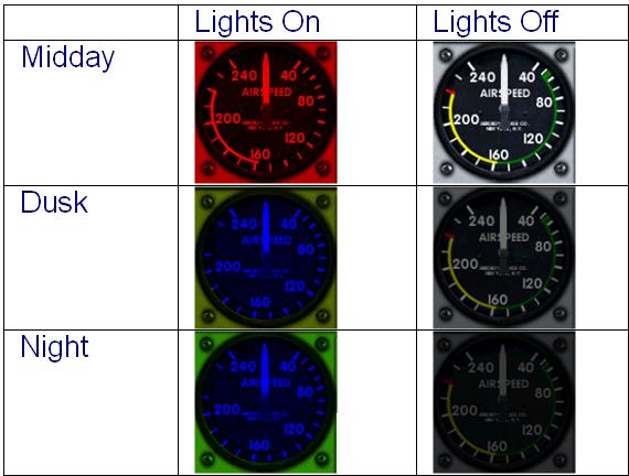
[color]
This section allows the default color lighting settings to be changed.
| Property | Description | Examples |
|---|---|---|
| day | The lighting color applied during daytime (RGB). | Day=255,255,255 |
| night | The lighting color applied at night (RGB). | Night=205,101,100 |
| luminous | The lighting color applied to gauges that are luminous (RGB). | Luminous=147,64,64 |
The day and night colors effectively determine the maximum and minimum brightness of the panel. Luminous specifies the color that can be applied to the luminous sections of the gauges. Here is an example to demonstrate what these colors mean. In this example, the colors for day, night, and luminous are red, green, and blue, respectively. Note the subtle difference between dusk and night – in this the environmental lighting system the height of the sun in the sky, moonlight, and so on, determines what percentage of the day color to use. When the lights are off no specified color is applied to the panel and its gauges however the brightness of the images are still affected by the environmental lighting.
[views]
This section enables the default views to be changed.
| Property | Description | Examples |
|---|---|---|
| view_forward_windows |
Identifies which panel windows display in the forward section of the aircraft. These
values must match the specific ident= value in the corresponding [windowXX] section. Valid
entries are: MAIN_PANEL RADIO_STACK_PANEL COMPASS_PANEL ANNUNCIATOR_PANEL ANNUNCIATOR2_PANEL COLLECTIVE_PANEL THROTTLE_PANEL MINI_CONTROLS_PANEL IFR_MAIN_PANEL GPS_PANEL OVERHEAD_PANEL |
|
| view_forward_dir | Enables you to change the default value of the view direction. Enter values for Pitch, Bank, and Heading. |
VIEW_FORWARD_DIR=-1.0, 0.0, 0.0 VIEW_FORWARD_DIR= 8.0, 0.0, 0.0 |
[fltsim]
| Property | Description | Examples |
|---|---|---|
| alias | The relative path from the Prepar3D root directory to the panel directory of the aircraft from which the panel should be an exact copy. |
Maule M7 260C Skis [fltsim] alias=\Maule_M7_260C\panel |